RetroComputerInstructionManual
IMSAI 8080 Programmed Output
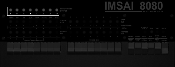
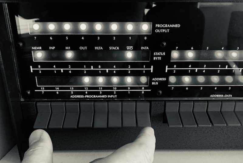
The IMSAI 8080 has a set of eight LEDs in the top left of the panel that are under software control.
These LEDs are very useful for testing and debugging when writing code - or for creating status lights, or a pretty blinkenlights display.
The LEDs are reached at port 255: writing a value to this port immediately changes which are turned on and off. You can write to this port directly in assembler, or from BASIC or in fact any other programming language.
There is one quirk with the LEDs: when you send a “1” to an LED, it turns off, and sending a “0” turns then on. This inverted display is a result of the internal electronics on the IMSAI - it kept the circuitry a little simpler. It’s easy to compensate in software though, as we’ll see:
Here are some coding examples in Microsoft BASIC:
10 REM BASIC EXAMPLE
20 FOR A = 0 TO 255
30 OUT 255, A
40 FOR B = 1 TO 200
50 NEXT B
60 NEXT A
70 GOTO 20
or taking the inverted nature into account:
10 REM BASIC EXAMPLE WITH INVERTED LEDS
20 FOR A = 0 TO 255
30 OUT 255, 255-A
40 FOR B = 1 TO 200
50 NEXT B
60 NEXT A
70 GOTO 20
Here’s a simple example in assembly language that writes a value to the LEDs. Try changing the value the A register contains (here it’s F0h).
MVI A, F0h
CMA
OUT FFh
JP 0000h
To enter this into the computer from the front panel, use the following pattern of switches.
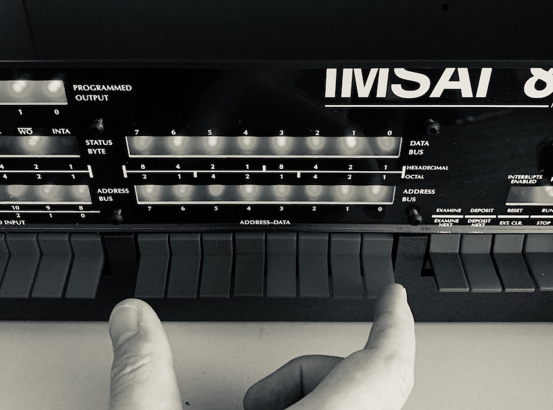
In the picture above, with all switches down, that would be
| 7 | 6 | 5 | 4 | 3 | 2 | 1 | 0 |
|---|---|---|---|---|---|---|---|
| 0 | 0 | 0 | 0 | 0 | 0 | 0 | 0 |
Here’s the sequence to enter:
- STOP
- Set all switches off
- RESET
Now work down this table, setting the switches and first toggling DEPOSIT and then DESPOSIT NEXT for subsequent entries.
| 7 | 6 | 5 | 4 | 3 | 2 | 1 | 0 | Switch |
|---|---|---|---|---|---|---|---|---|
| 0 | 0 | 1 | 1 | 1 | 1 | 1 | 0 | DEPOSIT |
| 1 | 1 | 1 | 1 | 0 | 0 | 0 | 0 | DEPOSIT NEXT |
| 0 | 0 | 1 | 1 | 1 | 1 | 1 | 1 | DEPOSIT NEXT |
| 1 | 1 | 0 | 1 | 0 | 0 | 1 | 1 | DEPOSIT NEXT |
| 1 | 1 | 1 | 1 | 1 | 1 | 1 | 1 | DEPOSIT NEXT |
| 1 | 1 | 0 | 0 | 0 | 0 | 1 | 0 | DEPOSIT NEXT |
| 0 | 0 | 0 | 0 | 0 | 0 | 0 | 0 | DEPOSIT NEXT |
| 0 | 0 | 0 | 0 | 0 | 0 | 0 | 0 | DEPOSIT NEXT |
- RESET
- RUN
Using RESET / EXAMINE / EXAMINE NEXT you can go back to address 0001h and change the F0h value to see what difference that makes.
You can combine using the LEDs at port 255 with reading the input value at port 255 - this value will be the state of the left-most set of the 16 address switches.
For example, here’s a BASIC program that will let you control the LEDs by flipping the switches.
10 REM MICROSOFT BASIC EXAMPLE TO READ SWITCHES
20 A = INP(255)
30 OUT 255, A
40 GOTO 20
In 8080 assembly language that would be:
IN 255
CMA A
OUT 255
JP 0000
Which would be:
- STOP
- RESET
- All switches down
| 7 | 6 | 5 | 4 | 3 | 2 | 1 | 0 | Switch |
|---|---|---|---|---|---|---|---|---|
| 1 | 1 | 0 | 1 | 1 | 0 | 1 | 1 | DEPOSIT |
| 1 | 1 | 1 | 1 | 1 | 1 | 1 | 1 | DEPOSIT NEXT |
| 0 | 0 | 1 | 0 | 1 | 1 | 1 | 1 | DEPOSIT NEXT |
| 1 | 1 | 0 | 1 | 0 | 0 | 1 | 1 | DEPOSIT NEXT |
| 1 | 1 | 1 | 1 | 1 | 1 | 1 | 1 | DEPOSIT NEXT |
| 1 | 1 | 0 | 0 | 0 | 0 | 1 | 0 | DEPOSIT NEXT |
| 0 | 0 | 0 | 0 | 0 | 0 | 0 | 0 | DEPOSIT NEXT |
| 0 | 0 | 0 | 0 | 0 | 0 | 0 | 0 | DEPOSIT NEXT |
- RESET
- RUN
This code inverts the LEDs, so a switch moved up makes the LED come on.